Donald Rumsfeld raised many eyebrows when he spoke about unknown unknowns. If you are a design engineer, you have a better appreciation for that comment than most people do. What may not be appreciated is the gap between application engineering and design engineering – here lurks the unknown unknowns.
Many of the unknowns discovered during the development phase will drive the final design. But are the reasons for the final configuration documented and parameter boundaries fully understood? During testing, are we unknowingly approaching the parameter envelopes that minor modifications in the future will allow expected use of the product to exceed the envelopes? To avoid being too abstract I will use an example where I nearly headed down the application path when a design program was required.
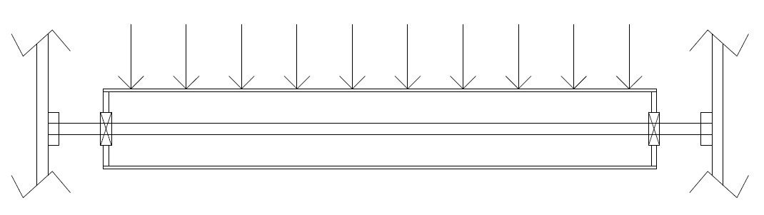
A web printing press uses a continuous length of paper (the web) guided through the machine by rollers. Our product used dead shafts to support rollers. Dead shafts are easily aligned in the field. This greatly reduces the precision required for manufacturing the support frames and the skills and equipment required during installation. The dead shafts are steel shafts with diameters ranging from one to two inches. A dead shaft does not rotate. The shaft is attached at each end to vertical frames that are parallel to each other. The roller body has ball bearings at each end with the inner race fixed to the dead shaft with setscrews. Our equipment, which we configured for a great variety of machines used rollers of various diameter and length combinations. Though the two parameters, diameter and length, had many combinations we remained within the parameter envelope and did not realize when we were approaching the limits. This often happens when a design is inherited (transferred from the design group to the application group) and an incomplete data trail exists to explain why the design is as it is.
The initial design accepted a web width of 40”. Later variations ranged from 26” to 80” wide. There was one parameter we did check each time and we were OK. There was another that we did not consider. We were always well inside the envelope at 40” and just pushing the envelope at 80” length but did not know it.
The parameter we were familiar with but never addressed for these applications was the axial alignment of the inner and outer races. The load on the roller induced by the web tension is surprising high. This is very much the case with a 180 degree web wrap which doubles the load. Our concern was always with the bending of the roller body not the shaft that supported it. Though the roller was a thin wall cylinder with end plugs for mounting the bearing’s outer race it had a diameter of 4 to 12” vs. the dead shaft of 1 or 2”. The moment of inertial of the roller body was magnitudes greater than the shaft. Loading on the roller body was evenly distributed by the web. The loading on the dead shaft was a point load at the bearings.
We were a fast turnaround shop. Often fire-ready-aim but good at it most of the time. When management wanted to go to 120” length rollers their expectation was just another two to three week application project vs. a design and development project which will take considerably more time. Design engineering and application engineering may look similar especially to the sales department but there is a difference. The difference can range from a fine line to a wide and deep canyon. When orders are coming in hand over fist, it is easy skip the assessment and in short time find your team as the bottom of that canyon.
Recalling the pain caused by those fire-ready-aim projects that went bad, I was able to insist on a proper study. One of the unknowns that became a known was the length limit for which dead shaft rollers are used. Too long and the bowing of the dead shaft creates too large of an angular misalignment of the bearing races. You can increase the shaft diameter but the shaft’s own weight causes it to bow with gravity. In short, at some point rollers needs to go to live shafts and at 120 inches we were way past that point.
Live shafts require bearings mounted in the support frames that required machining accuracies that would have turned the entire product line on its ear. Someone likely picked the dead shaft approach early on and so much of the design and installation became depended on it. That simple fact of inner race to outer race angular alignment had a major ripple effect on the entire design and alignment process during installation.
My study was fast and dirty. How close I was to a true budget and schedule will never be clear. The study clearly indicated the effort we faced was not just another application. Had we proceeded we would have quoted prices and schedules that would have proved impossible to meet. The resources to develop the design were too great and the project dropped with minimal resources expended.
I was able to do the study very quickly using a method I watched an old sage use to put together a multimillion-dollar budget estimate in less than two hours. I later come to learn I was using the Fermi estimation method. Fermi estimation is a powerful tool and would make a good article for the future.
Many of the unknowns discovered during the development phase will drive the final design. But are the reasons for the final configuration documented and parameter boundaries fully understood? During testing, are we unknowingly approaching the parameter envelopes that minor modifications in the future will allow expected use of the product to exceed the envelopes? To avoid being too abstract I will use an example where I nearly headed down the application path when a design program was required.
A web printing press uses a continuous length of paper (the web) guided through the machine by rollers. Our product used dead shafts to support rollers. Dead shafts are easily aligned in the field. This greatly reduces the precision required for manufacturing the support frames and the skills and equipment required during installation. The dead shafts are steel shafts with diameters ranging from one to two inches. A dead shaft does not rotate. The shaft is attached at each end to vertical frames that are parallel to each other. The roller body has ball bearings at each end with the inner race fixed to the dead shaft with setscrews. Our equipment, which we configured for a great variety of machines used rollers of various diameter and length combinations. Though the two parameters, diameter and length, had many combinations we remained within the parameter envelope and did not realize when we were approaching the limits. This often happens when a design is inherited (transferred from the design group to the application group) and an incomplete data trail exists to explain why the design is as it is.
The initial design accepted a web width of 40”. Later variations ranged from 26” to 80” wide. There was one parameter we did check each time and we were OK. There was another that we did not consider. We were always well inside the envelope at 40” and just pushing the envelope at 80” length but did not know it.
The parameter we were familiar with but never addressed for these applications was the axial alignment of the inner and outer races. The load on the roller induced by the web tension is surprising high. This is very much the case with a 180 degree web wrap which doubles the load. Our concern was always with the bending of the roller body not the shaft that supported it. Though the roller was a thin wall cylinder with end plugs for mounting the bearing’s outer race it had a diameter of 4 to 12” vs. the dead shaft of 1 or 2”. The moment of inertial of the roller body was magnitudes greater than the shaft. Loading on the roller body was evenly distributed by the web. The loading on the dead shaft was a point load at the bearings.
We were a fast turnaround shop. Often fire-ready-aim but good at it most of the time. When management wanted to go to 120” length rollers their expectation was just another two to three week application project vs. a design and development project which will take considerably more time. Design engineering and application engineering may look similar especially to the sales department but there is a difference. The difference can range from a fine line to a wide and deep canyon. When orders are coming in hand over fist, it is easy skip the assessment and in short time find your team as the bottom of that canyon.
Recalling the pain caused by those fire-ready-aim projects that went bad, I was able to insist on a proper study. One of the unknowns that became a known was the length limit for which dead shaft rollers are used. Too long and the bowing of the dead shaft creates too large of an angular misalignment of the bearing races. You can increase the shaft diameter but the shaft’s own weight causes it to bow with gravity. In short, at some point rollers needs to go to live shafts and at 120 inches we were way past that point.
Live shafts require bearings mounted in the support frames that required machining accuracies that would have turned the entire product line on its ear. Someone likely picked the dead shaft approach early on and so much of the design and installation became depended on it. That simple fact of inner race to outer race angular alignment had a major ripple effect on the entire design and alignment process during installation.
My study was fast and dirty. How close I was to a true budget and schedule will never be clear. The study clearly indicated the effort we faced was not just another application. Had we proceeded we would have quoted prices and schedules that would have proved impossible to meet. The resources to develop the design were too great and the project dropped with minimal resources expended.
I was able to do the study very quickly using a method I watched an old sage use to put together a multimillion-dollar budget estimate in less than two hours. I later come to learn I was using the Fermi estimation method. Fermi estimation is a powerful tool and would make a good article for the future.
 RSS Feed